
Progress with the Eaglemoss/Die-Cast Club build of the 1:8 Mercedes-Benz 300 SL is definitely coming along! This chapter will focus on the engine assembly and then on mounting the physical beast to the frame.
It’s not all roses, and dammit, sometimes I wish I had an extra hand or two LOL… Guide #3’s primary focus is the engine build. For the most part, it went along smoothly; however, I did find an error with the guide. Read on to learn more. Guide #4 is more with the engine build and transmission area, with the remaining task of mounting the finished motor to the frame. Exciting, I know! If you’re curious, the chassis in length is 19 inches, and the motor /intake hose stretches 8 inches. Huge, I know!
Any questions or comments, please let us know, we’ll do our best to answer or get you an answer if beyond our scope of knowledge. The next chapter in the series will be #5. Here we tackled some secondary frame structures and installed our first suspension bits. Stay tuned!
GUIDE #3
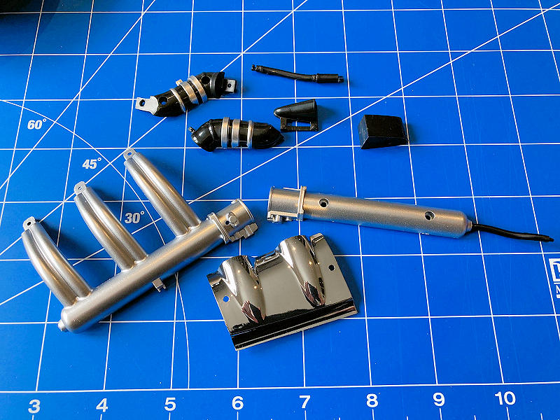
ENGINE CYLINDER HEAD/INTAKE HOSE
The parts here are mostly plastic with the exception of the main engine cylinder head, which is cast in metal.
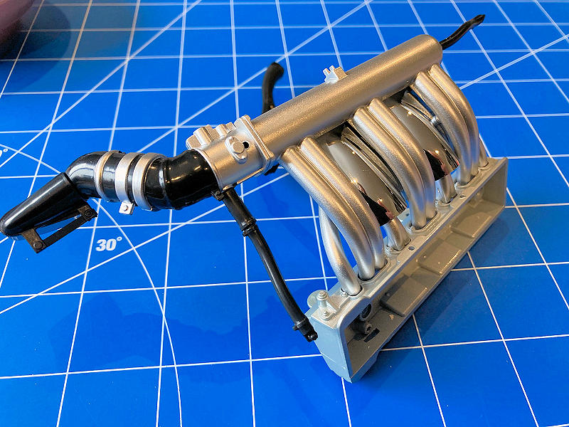
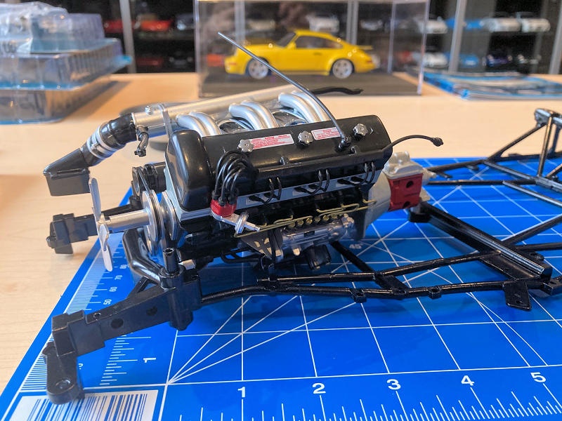
The engine intake hose is the second step. Note the quality parts and the finished work on the chromed bits. All went together here without a hitch. The next photo will provide a look at the finished product.
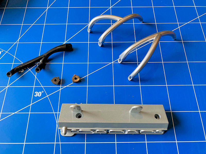
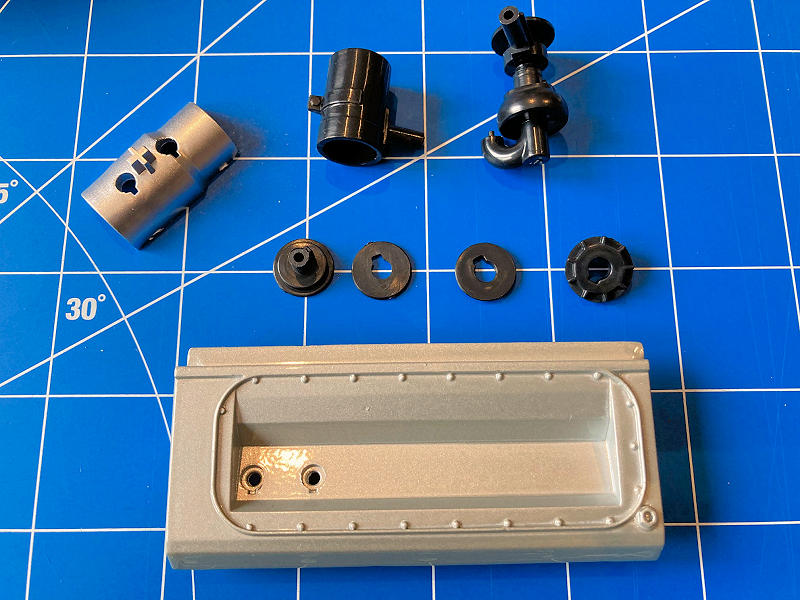
CYLINDER HEAD COVER/DISTRIBUTOR
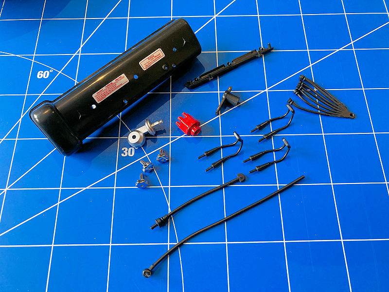
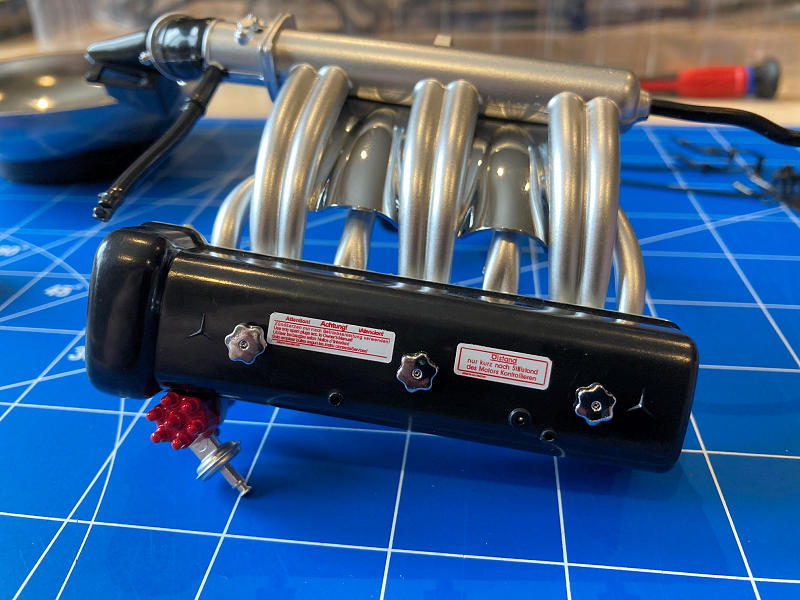
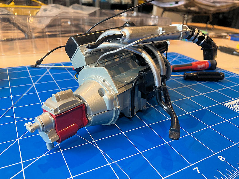
Cylinder head parts above. Everything here is made of plastic; some are more rigid and others more flexible, i.e distributor cables. Again, fit and finish are very good. The second photo highlights the assembled product with intake. Note the attention to detail with the OEM labels on top of the cylinder head cover with accompanying three oil filler caps.
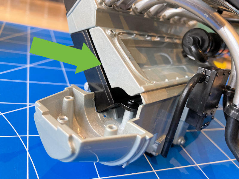
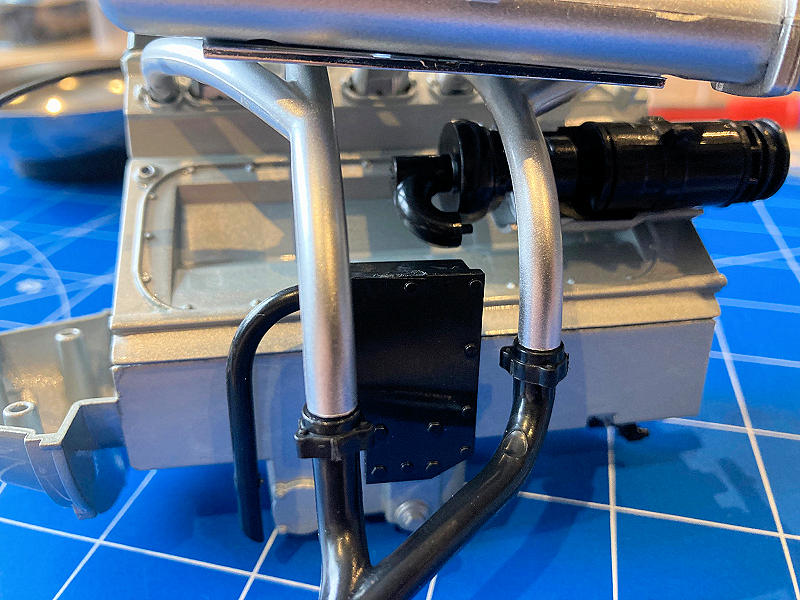
The next step is mounting the above to the left engine block. We did find an error with the provided instructions, though. It states to use the larger of the two holes; well, this is incorrect; the correct holes are noted with Green arrows below.

Putting the ignition cable casing together wasn’t too terrible. The biggest challenge was keeping it all in place once installed.
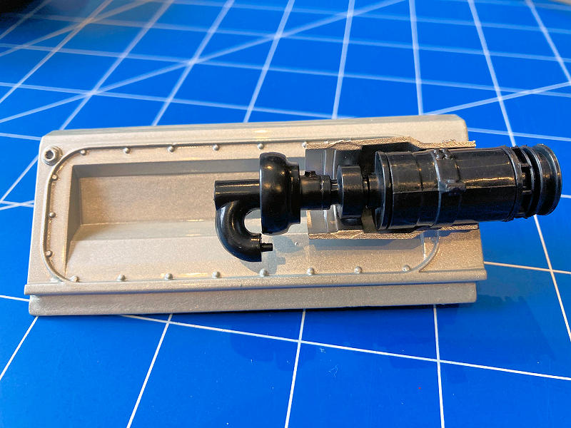
TIP: Use a little piece of painter’s tape to hold the casing in place once installed. It will allow you to manipulate the part while assembling the remaining pieces of the puzzle for this stage. See the photo below.
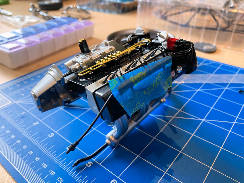
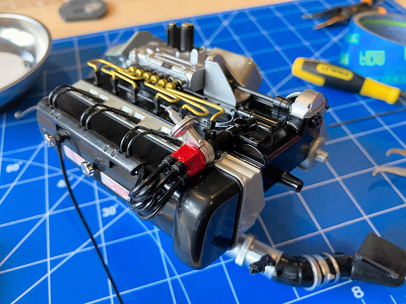
Finish piece. What do you think? Note, there is no specific instruction for the firing order of the ignition cables. I chose a random pattern, which I believe looks more authentic and real.
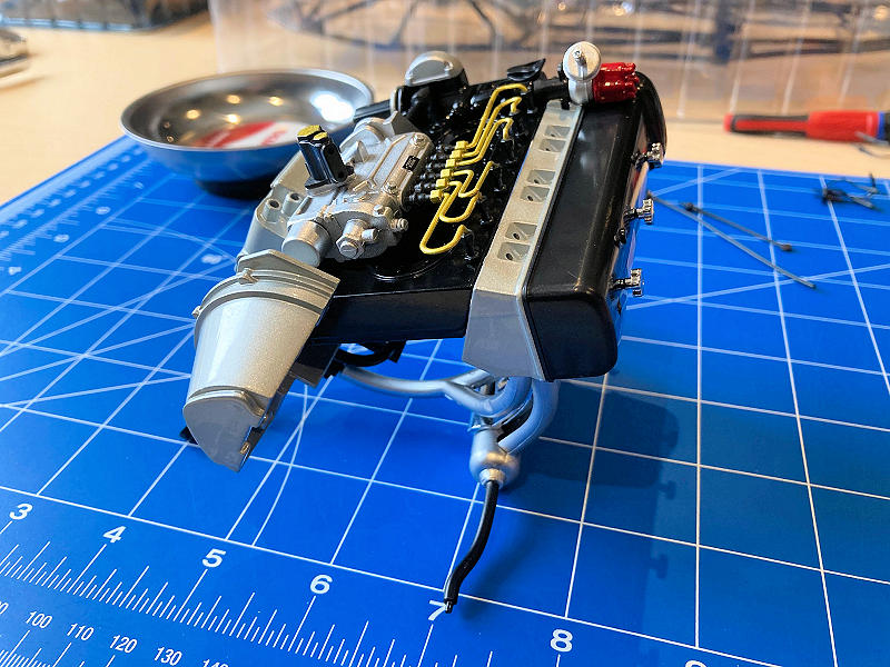
ALTERNATOR/WATER PUMP
This section is straightforward. Parts here are all plastic, with the exception of the right side of the engine block.
I’m not going to lie. Marrying the right engine block to the left did take a few attempts. Keep calm and deliver, the two sides do fit! Also, don’t be concerned with the gap as noted below. This area will eventually be covered with the clutch housing in guide #4.
GUIDE #4
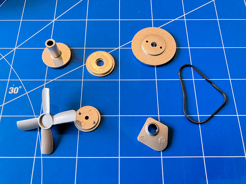
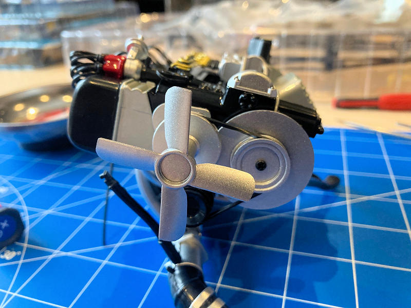
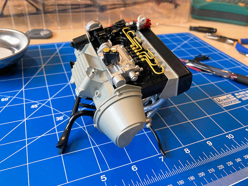
ENGINE FAN
Any cool car model will require some cooling. The parts for this step are shown below. Each piece is fabricated from plastic. Assembly at this phase is pretty straightforward and drama-free.
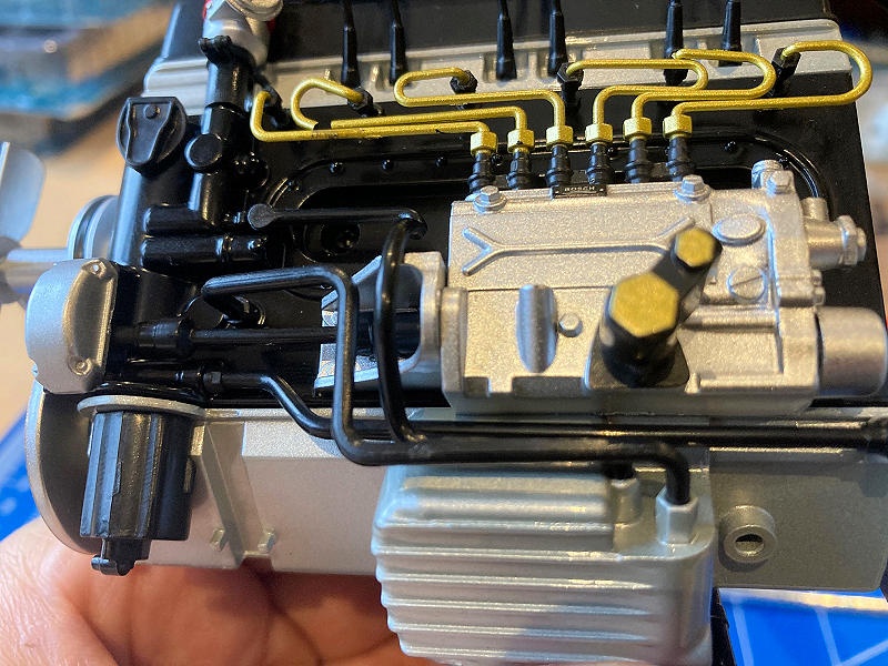
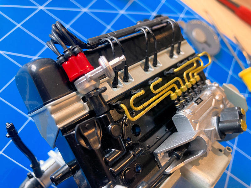
OIL LINES AND RELATED
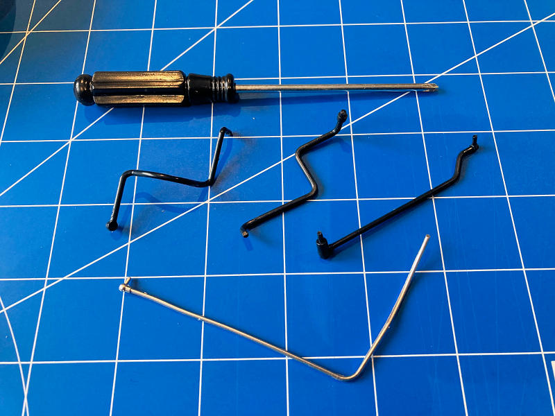
At this point, the kit provides a pair of Phillips screwdrivers. This one is smaller than the first. The single Silver item is the high-pressure oil line.
This was more challenging than I suspected initially. One of the three oil lines required more attention than the rest; location and fat fingers did not help. I used a PicTool, as shown before, to slightly clean out the indented home. It worked!
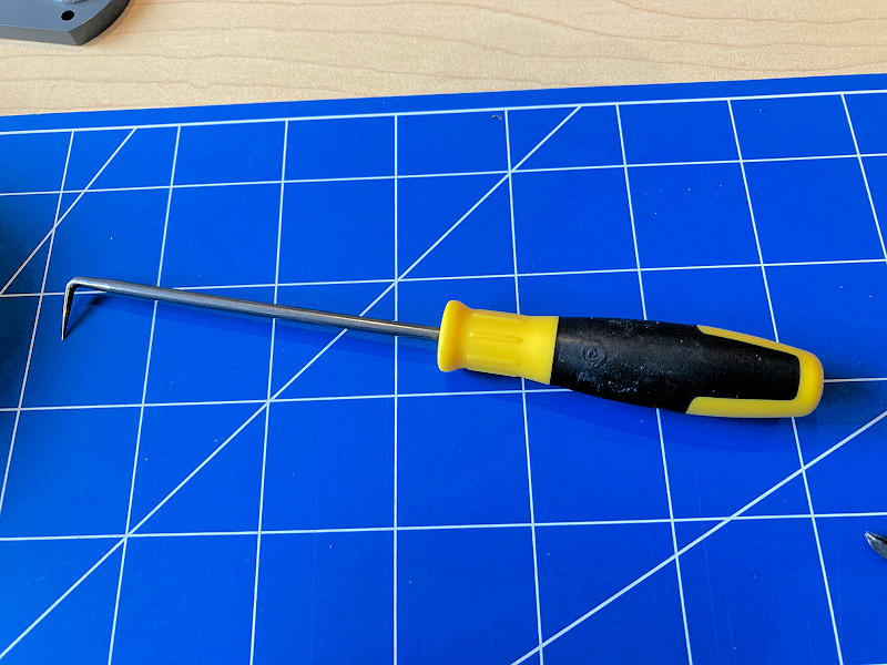
TIP: Use a pic-tool to help clean and open up small surfaces where the required part does not seem to fit or a file cannot access.
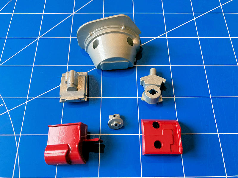
GEARBOX AND CLUTCH HOUSINGS
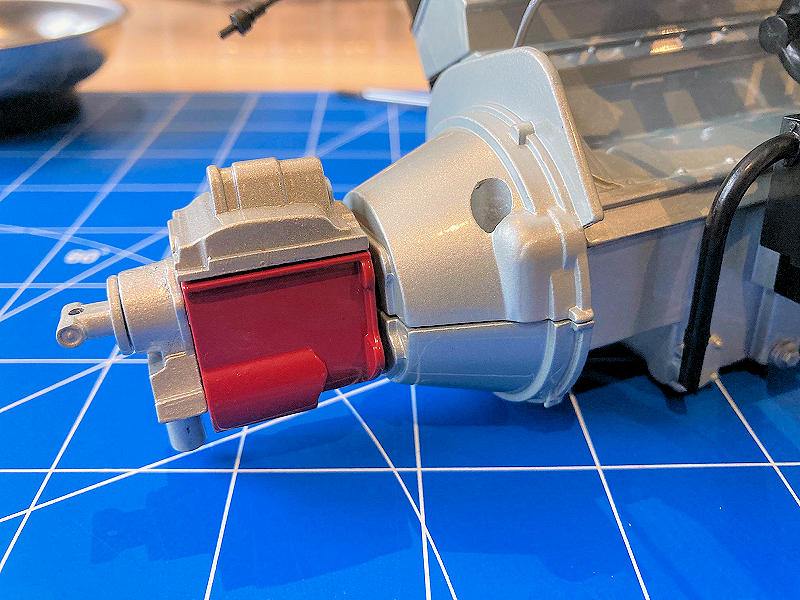
All applicable parts here are cast in metal. Fit and finish are quality throughout. The assembled pieces are shown in figure two below.
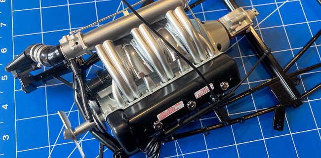
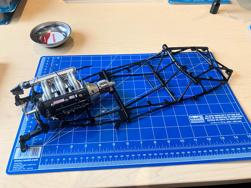
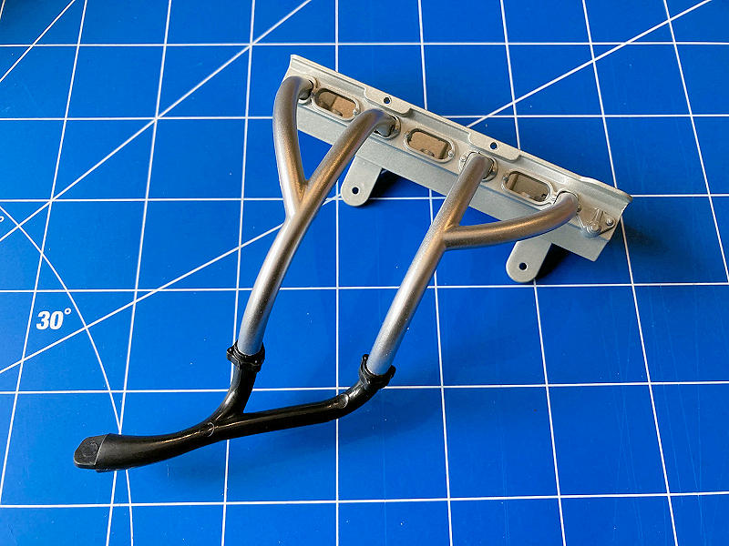
FITTING ENGINE TO CHASSIS
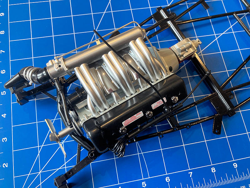
The final part of guide #4 is fitting the complete motor and transmission to fame. This is relatively simple. The biggest challenge is not to damage the assembled motor, specifically the finer detail of the surrounding pieces.
The frame is all metal and painted Black. Two screws support the motor to the frame. Nice to see that each screw used is mated from one metal component to another metal component. All feels solid and secure and will definitely provide longevity to the finished product.

Thanks for an interesting series. I have one small comment. The three knurled knobs on the cylinder head cover are not oil filler caps, but rather the bolts that hold the cover onto the head. The 300SL has a dry sump system so that the oil is added to a large oil tank which presumably will be added to the model later.
Yes, definitely not the norm of news and reviews. Thanks for the insight. I’m no history authority on the 300 SL, and this is how they were defined by Eaglemoss/Die-cast Club. I guess they need to update the guide #3 :)